Firmware Boot Process
In Section 11.1.1, we introduced that the starting address of the first entry in the partition table is 0x9000. But why is the starting address not 0x0? And why is it 0x9000? To answer these questions, let's first look at Figure 11.3, which presents the specific contents stored in a 4 MB flash.
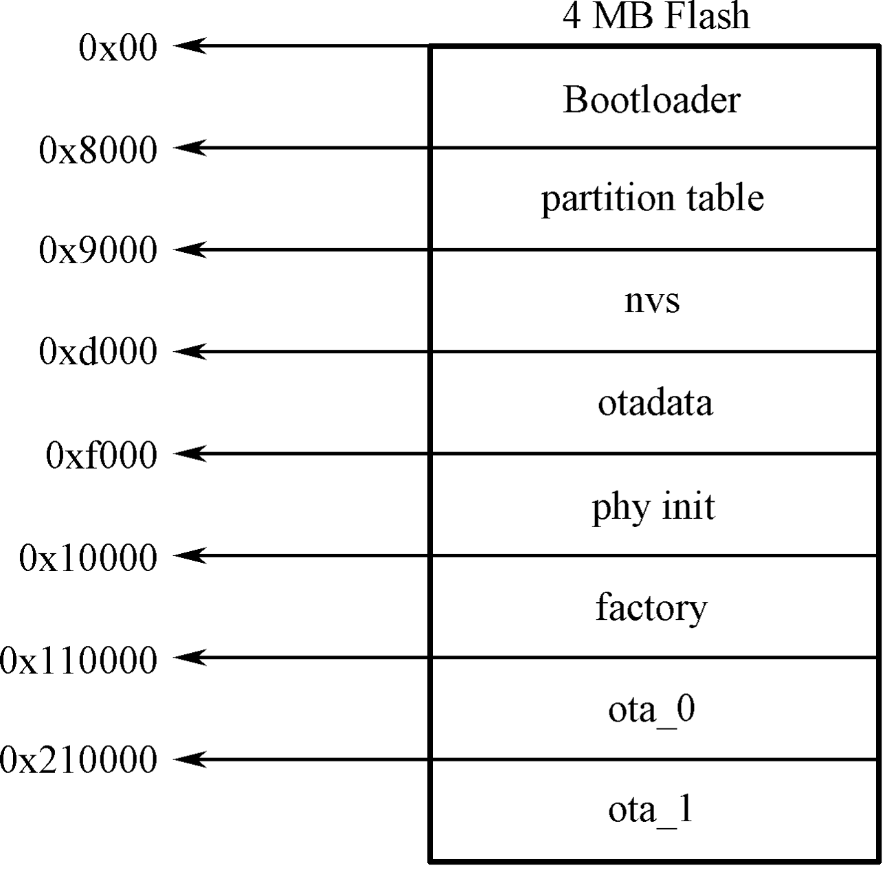
As can be seen from Figure 11.3, the flash is divided into eight areas: the address 0x00 stores the Bootloader, the address 0x8000 stores the partition table, and the latter 6 areas, starting from 0x9000, is the area divided by the partition table, which you may already be quite familiar with. Now we can answer the first question. The reason why 0x0 is not the starting address is that it stores the Bootloader (not every 0x0 address of the chip flash stores the Bootloader. ESP32 series chips store the Bootloader at 0x1000), which is used to load and boot the application partition. In the programming design of Espressif chips, Bootloader is called the secondary bootloader, which mainly increases the flexibility of flash partition and facilitates the implementation of flash encryption, secure boot, and OTA functions. The secondary bootloader loads the partition table from the offset address of flash at 0x8000 by default. The size of the partition table is 0x1000. The secondary bootloader will look for the factory application partition and the OTA data partition from the partition table and determine which partition to boot by querying the OTA data partition. Therefore, the second question has also been answered.
The process from power-up to running the app_main() function on
ESP32-C3 can be divided into three steps:
-
Bootstrapping is performed by the primary bootloader, which is stored in the ROM of the ESP32-C3. Upon the chip reset, the CPU starts running immediately to determine the boot mode and perform relevant operations. The secondary bootloader is then loaded into RAM from the offset address 0x0 of the flash.
-
Bootstrapping is performed by the secondary bootloader. The secondary bootloader will first load the partition table from flash and then query the OTA data partition to select a firmware from a particular application partition for loading. When all data is processed, the secondary bootloader will verify the integrity of the firmware and look for the entry address from the header of the binary firmware file, and then jump to that address to execute the firmware. The firmware in the application partition has certain statuses that affect its startup. These statuses are stored in the OTA data partition and are defined in ESP-IDF by a set of enumerated variables (
esp_ota_img_states_t).-
New firmware: defined by
ESP_OTA_IMG_NEW, indicates whether the firmware is being loaded by the Bootloader for the first time. This status will be changed toESP_OTA_IMG_PENDING_VERIFYin the Bootloader. -
Pending-for-verification Firmware: defined by
ESP_OTA_IMG_PENDING_VERIFY, indicates whether the firmware has been enabled. If the firmware remains in this status on the second boot, the status will then be changed toESP_OTA_IMG_ABORTED. -
Valid firmware: defined by
ESP_OTA_IMG_VALID, indicates that the firmware is functioning normally. Once marked with this status, the firmware can be booted without restriction. -
Invalid firmware: defined by
ESP_OTA_IMG_INVALID, indicates that the firmware is not functioning properly. Once marked with this status, the firmware cannot be rebooted. -
Aborted firmware: defined by
ESP_OTA_IMG_ABORTED, indicates that there is an exception with the firmware. Once marked with this status, the firmware cannot be rebooted. -
Undefined firmware: defined by
ESP_OTA_IMG_UNDEFINED. Once marked with this status, the firmware can be booted without restriction.
-
-
Application startup phase. After the bootstrapping performed by the secondary bootloader comes the application firmware startup phase, which includes all processes from the start of the application to the creation and execution of the
app_main()function. This phase can be divided into three parts:-
Initialisation of hardware and basic ports.
-
Initialisation of software services and the FreeRTOS system.
-
Running the main task and calling the
app_main()function.
-